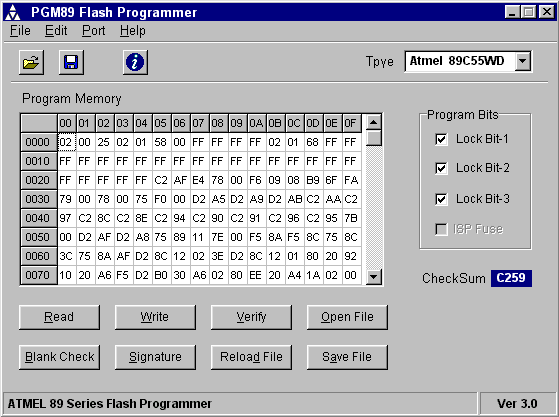
Atmel 89 Series Flash Programmer Ver 3.0 ATMEL 89 Series Flash Microcontroller Programmer Ver 3.0 M Asim Khan, Introduction This programmer was designed in view of to be flexible, economical and easy to built, the programmer hardware utilizes the standard TTL series parts and no special components are used. The programmer is interfaced with the PC parallel port and there is no special requirement for the PC parallel port, so the older computers can also be used with this programmer. Supported Devices The programmer software supports the following Atmel devices AT89C51 AT89S51 AT89C51RC AT89C1051U AT89C52 AT89S52 AT89C55WD AT89C2051 AT89C55 AT89S53 AT89S8252 AT89C4051 Note: For 20 pin devices a simple interface adapter is required. Hardware Figure 1 shows the circuit diagram of the Flash Programmer, the programmer is interfaced with the standard parallel port of the PC.
As shown in the diagram U2 is used to control the data flow between the controller and the PC, U4 latched the low order address byte and U5 latched the high order address byte, while U3 is used to generate the control signals for micro controller to be programmed. IC U1 is used to generate the progrram pulse for the u-controller.


The power supply section uses U8 to generate the logic 5V supply while the U7 is used to provide the programming supply voltage to controller. IC U6 is used to generate the VDD power supply voltage for the u-controller which is selectable either 5v or 6v5. The power to the circuit is provided by a wall adapter of 15 to 18V output, normally a 15V type adapter will provide a 19~20V output voltage. As shown in the diagram the crystal X1 can be replaced by a resonator in that case capacitors C4 and C5 are not required. Place a small heatsink on U8 voltage regulator.
Introduction This ISP Programmer can be used either for in-system programming or as a stand-alone spi programmer for Atmel ISP programmable devices. Snow Leopard Torrent Download Iso.
For the adjustment of P1, P2 and P3 use a digital multimeter & follow the steps shown below, 1. To adjust P1, temporarily connect T1 base to ground using test clips then adjust P1 to get 6.5V at the output of regulator U6. Next first adjust P2 to get the 13.1V at the output of regulator U7, make sure transistor T5 is off or temporarily connect the T5 base to ground using test clips. Now temporarily short the collector of transistor T5 to ground using test clips. Adjust P3 to get the 12.1V at the output of U7 regulator IC. Figure 1: Circuit Diagram of Flash Programmer V3.0 Figure 2 shows the circuit diagram of the interface adapter card required for the programming of 20 pin Flash devices. Figure 2: Interface Adapter circuit diagram V3.0s Constructing the Board The prototype board may be built using universal PCB with point-to-point wiring.